Saturday, August 27, 2005
Fuel filler neck
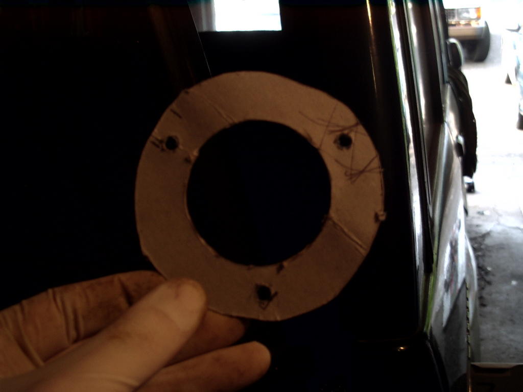
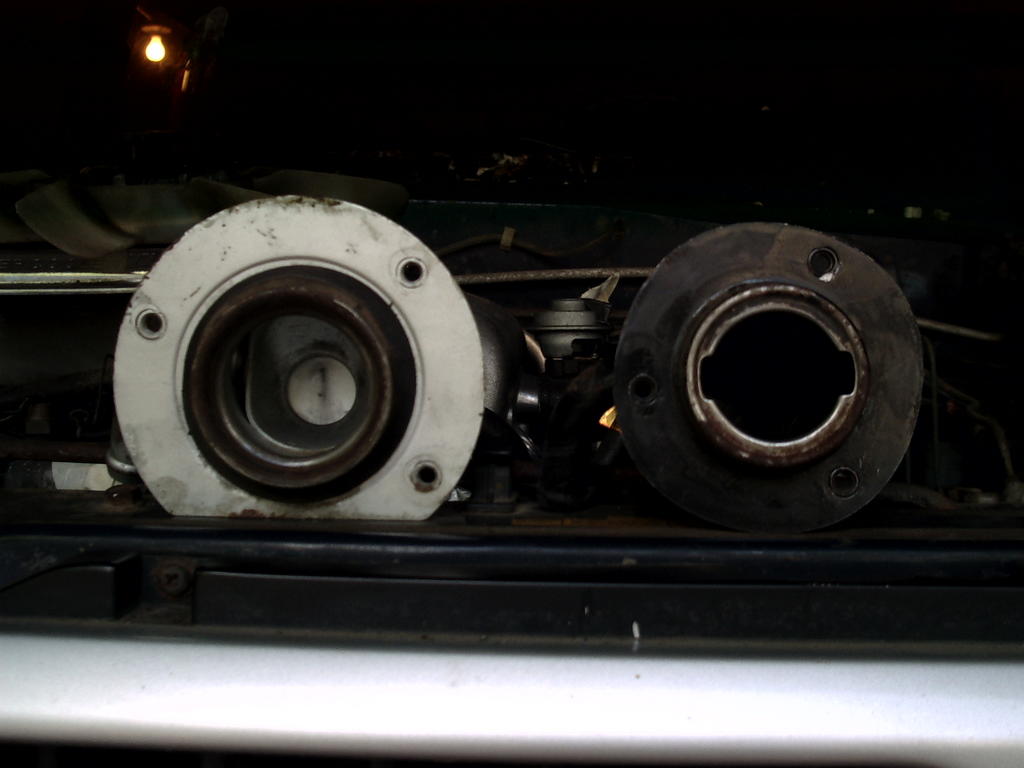

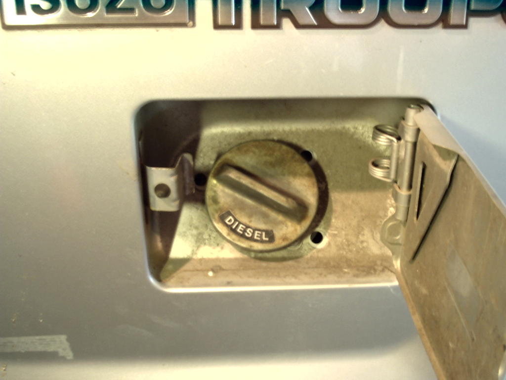
These photos show the diesel filler neck I purchased (originally from an '86 Trooper diesel) next to the gasoline neck from the '88. The mounting flange and holes are different, so I made up a cardboard pattern and drilled the body to match the diesel neck. The third shot is of the new set of holes, and the final shot shows the finished product. I also peeled the 'unleaded fuel only' sticker off the inside of the fuel door, which felt pretty good ...
The diesel neck has an extra port on it, which I assume is a vent, in addition to the large drainback port present on both necks. I plan to route a hose from this port to a weather-safe location and vent to atmosphere. Diesel is much less volatile than gasoline, so all the vapor recovery ports on the tank will be plugged and related systems removed. I'll detail the other fuel system modifications in a later post.
Shift levers and driveshafts


Here are a couple of quick shots showing the drive shafts before and after modification. After taking measurements from the transmission crossmember, I determined that the shafts each had to be altered by 1-13/16" -- the rear had to be shortened at the transmission end, and the front had to be lengthened -- due to the transmission having moved rearward by this amount. The rear is now in and looks to fit well. I have yet to install the front shaft, but anticipate no problems.
The last photo shows the shift levers (the ones that came with the truck were re-used -- the diesel transmission lever was bent for shipping ease and destroyed, and the transfercase lever was shaped differently and interfered with the center console, so I used the US gasoline chassis levers) and their positioning. The transmission shift lever looks close to the console because it's in 2nd gear in the photo. The console clearance is tighter than it was, but everything fits and feels fine after sitting in the driver's seat and running through the gears. The gas transmission lever had a slightly different end than the diesel version, as there was a guide 'bump' on it not present on the diesel lever. The diesel shift tower has the channel to accommodate this, however, and it seems to work fine, so I am not sure why the difference between them.
Thursday, August 25, 2005
Navigational Aid
Photos can be viewed full-size by clicking on them, and older posts can be accessed by using the monthly links on the right (under 'archive'). Thanks for the interest.
Monday, August 22, 2005
Transmission mounting
As usual, click images for larger versions.
The drivetrain is in except for the driveshafts, which have been modified and are ready to be reinstalled.
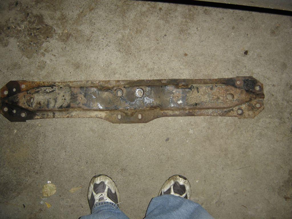
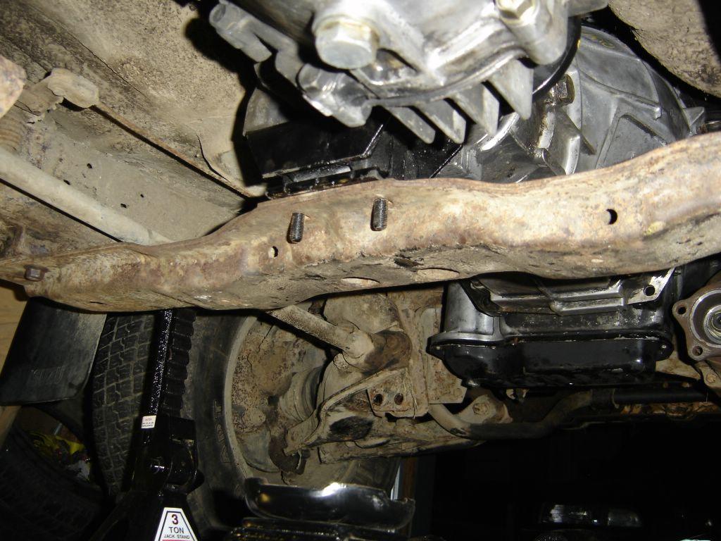
The top shot is of the transmission crossmember. It is symmetrical about the long axis with the exception of the extra set of mount holes drilled in an extended area shown at the lower edge in the photo. These are the mount holes needed to mount the diesel transmission, as mounting the engine using the stock diesel mounts places it about 1-13/16" rearward of where the gas transmission was.
The crossmember needs to be rotated 180* and reinstalled to use these extra holes. There are driveshaft cutouts on both sides of the crossmember, as well as bolt holes for the bash guard (although they aren't tapped on the unused side, so I'll have to figure something out - large sheetmetal screws?) , so it's obvious Isuzu meant for it to be flipped around depending on application. This is the key to a bolt-in installation.
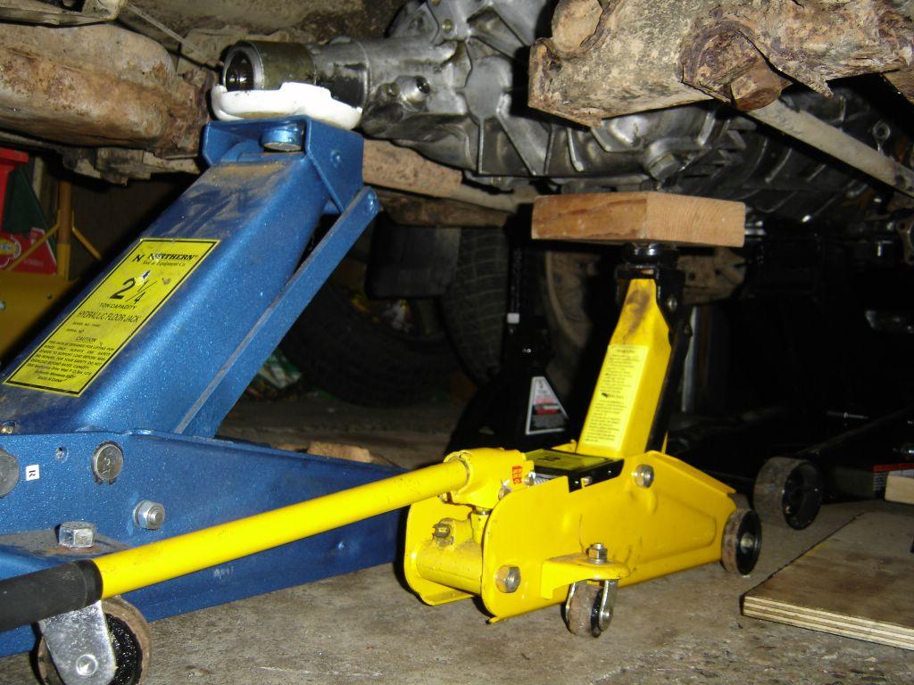
Second shot is of the three jacks it took us to get the transmission installed (black jack under bellhousing is barely visible). The diesel bellhousing has got the starter motor 'bump' on the opposite side as compared to the gas unit, so simply lifting the transmission up and in results in the bump hitting the body of the truck before it can mate properly with the engine.
The procedure to get it installed correctly requires the transmission be rotated as it is raised. We accomplished this by using three floor jacks, two large (3-ton) and one small. The large jacks were positioned under the bellhousing and tailshaft, while the small one was under the transfer case to be used as a rotational aid. I still had to lay underneath and bench press the bellhousing to help it rotate and to check alignments.
The transmission should be rotated about 90* clockwise (looking at the flywheel side of the engine, which is where you'll be when doing this!) so the starter bump is up in the tunnel of the body. Get it as close as possible, then rotate the transmission back until it's about 45* past its normal mating position to get it the rest of the way in, rotating it back to the correct location as it's shoved onto the clutch assembly. This process is a pain, but it won't go on without rotating as it interferes with the body.
I also pounded the exhaust shield back to allow for more clearance. Another trick we employed was to use a long 2x4 board to lift the transmission up before sliding the jacks under it (one end of the board stuck out on either side of the truck, so 2 people could grab the ends and lift the transmission up).
Final shot is of the diesel transmission sitting on the (rotated) crossmember, using the stock mount.
Wednesday, August 10, 2005
Transmission
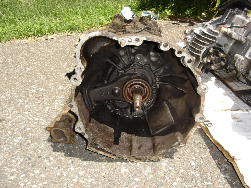


Attached are shots of the two transmissions. The gas unit is the dirty one. They are identical from the rear of the bellhousing back. The clutch release and starter are on opposite sides, which means that the diesel bellhousing is needed (at least) to use the 4JB1-TC engine.
Crossmember bolt blues

Remember the frame crossmember bolts? I had broken three of them off in the frame while trying to remove them. There are four on each side, and while one side had four good ones, the other had only one.
Drilling resulted in a bit being broken off in one stump, and an extractor being broken off in another. Welding nuts onto the remains proved futile in getting them out. What to do?
I hadn't noticed, but there are 2 holes in the frame situated between the crossmember bolt holes. Drains? I don't know, but I decided to put them to use. I drilled the crossmember so it had holes to match, and bought some grade 8 hardware to attach it with. After tapping the frame holes, cutting the bolts with a die, and adding my new holes, the crossmember will be as sturdy as it ever was. I think if I had broken all 8 bolts off, drilling 4 new holes and using only 2 bolts on each side would hold it without hassles. These bolts are pretty tough.
I did end up drilling the opposite side of the crossmember, as I planned on reinstalling it 180 degrees rotated from its original position. Why? Read on...
Attached is photo of the new holes to give a better idea of what I'm talking about.
Tuesday, August 09, 2005
Engine is in!


Been a while since the last update... much has happened. The engine is in -- after much deliberation as to whether or not to build custom mounts, it was decided to try the mounts it came with. Glad I did.
After some measuring, it was determined that while the 4JB1-TC mount pads would bolt directly to the frame, it would place the rear edge of the block about 2" rearward of where the rear edge of the gas block was originally (as measured from the mount pads on both engines). This would then shift the transmission rearward by the same amount, which I thought was a bad idea as it would cause the rear crossmember transmission mount not to line up.
I considered building custom engine brackets to get the engine forward about 2", but this would necessitate the use of an electric radiator fan, as the mechanical fan would be too far forward. At this point, I heard from the Isuzu guru himself, Mr. Lemond, that the crossmember had an extra set of mount holes that may accomodate the rearward mounting of the transmission (I hadn't seen these, as my crossmember was still attached to the old transmission - one of the mount bolts needed to be torched off. Had this done promptly after hearing of the extra holes...). Things are getting interesting...
We then decided to try mounting the engine in the truck using the mounts it came with, which resulted in what seemed to be perfect placement of the engine. The mechanical fan looked like it would clear the radiator, and it sat in the bay just like stock. Even the heater hoses line up! Time to try our luck with the transmission.
Here are a couple of shots of the engine sitting in the bay. Click the images for a large version (this applies to all images on the site, by the way).