Sunday, November 27, 2005
Throttle cable
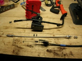
Below are a few shots of the completed throttle cable. The stock (gas engine) cable was much too long for the diesel, as the intake sides of the engine are different. Also, the engine-side bracket was wrong on the gas cable. The diesel engine came with about 5" of cable, cut short during removal by the wreckers no doubt. Even if it were complete, I am sure it was from a right-hand-drive vehicle and would have been much too long for the new chassis anyway.
I bought the stainless braided universal throttle cable at a local speed shop. It had an engine-side end made for a carburetor, but was otherwise well suited to the application.
The upper left photo shows all the parts together. It was about twice as long as I needed, so it was cut back to fit.
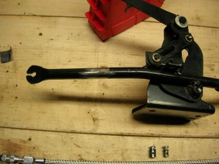
The upper right is a shot of the pedal assembly. I cut the cable receiver off and welded it back on 90* rotated from its original position to accommodate the shackle that the new throttle cable employs (originally, the cable met the pedal with an in-line rubber cylinder, which was more difficult to duplicate than it was to modify the pedal to accept the new cable end). It fits perfectly, as luck would have it.
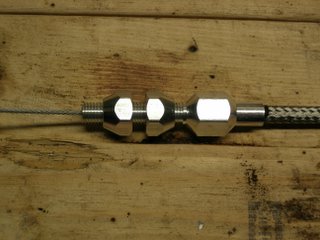
The second row photos are of the engine-side cable retainer nuts (left) and pedal-side shackle and firewall mount (right). I added the washers to secure it in the firewall, as the hole is larger than the cable mounting nuts. The engine-side retainer fits just like the stock cable retainer, no modifications needed.
The lower left photo shows the cable wire stops I bought, along with the stock end of the gas throttle cable (diesel is identical). My good friend Tom, who has been helping me with advice and labor throughout the project (couldn't have done it without the assistance!), found these wire stops advertised on a go-kart parts site.
I wanted to duplicate the Isuzu engine-side end, also shown in the photo. It is similar to a bicycle brake cable, only taller. The go-kart wire stops employ set screws to hold them to the throttle cable's inner wire, and seemed perfect for the task. I found some locally at a small engine repair shop - 2 for 50 cents! At any rate, the wire stop on the left is shown with the Isuzu bushing from the diesel cable installed over it. The center wire stop is as purchased, and the rightmost cable end is the Isuzu part.
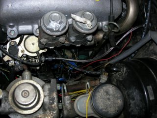
The lower right photo is a shot of the completed installation. I just need to free up the pedal stop bolt, on the driver's footwell, so I can adjust it properly to the shorter travel the diesel engine requires. A few days soak in penetrating oil should do it.
Throttle cable images - click to enlarge
Tuesday, November 15, 2005

A photo of the injector pump and candidates for the cutoff solenoid. Photo posted for discussion on the 4x4wire site.
Dash completed


A couple of quick shots of the re-installed dashboard. The careful observer will note the (approximately) 4200 RPM redline diesel tachometer, glow indicator lamp near the defroster button (to the left of the wheel) and the warning lamp for a full sedimenter (lower left idiot light), part of the full diesel warning lamp cluster.
As always, click images for full-sized versions.
Glow plug resistor, part 2
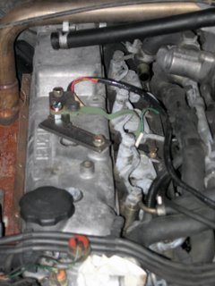
 Shown here is the mounting bracket fabricated for the 'sensing resistor' for the glow system. The bracket bolts to two unused holes in the valve cover. The resistor (a metal strip with wires attached) was bent slightly to meet the bracket and the glow power bus. Note the nut used as a spacer so it doesn't short to the bracket - I forgot to check the clearance before I welded the captive nut on the underside and it was touching the bracket (too concerned about it clearing the intercooler, which it does by miles).
Glow plug resistor


Shown here is the bracketry & mounting position of the 'dropping resistor' (as Isuzu calls it) for the glow system. On low power glow, current flows through this resistor before going to the plugs. I decided to mount it with plenty of clearance to facilitate the shedding of heat. It bolts to the fender using the fuse box bolt on one side and an open threaded hole beneath the hood hinge on the other side. Unfortunately, the photo doesn't clearly show the angled bits of the more complex bracket, of which I'm proud...
Fuel system complete
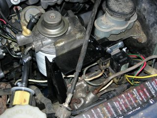

Here are two shots of the fuel filter/water separator/primer pump mounting bracket completed, painted and installed. The glow plug relays are mounted to the top and can be seen in the second shot. Also visible is the pre-filter (at $1.99, much cheaper to replace than the main filter at $27 if something nasty comes up from the tank!) I installed. The fuel system is now complete.
